Introduction
During the firmware development of my embedded controller, I wanted to start adding some more complicated sensor support; something beyond just a 0 to 3.3V analogue signal. I had used the DHT11 before, and its quite inexpensive too, so I wanted to see if I could create a “from scratch” driver for it, working with the individual bits, as it would be a good primer before I started trying to do the same but for the whole of MODBUS RTU.
The DHT11
The DHT11 is a basic, low cost digital temperature and humidity sensor. It uses a capacitive humidity sensor and a thermistor to measure the surrounding air, outputting a digital signal on its data pin [1]. As it is not an analogue sensor, the readings are encoded in binary and sent one bit at a time, so a driver is required to decode this data.
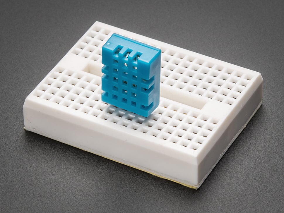
The DHT11 has four pins, although only three are used. Pin 1 is VCC (+) which is rated for 3.3V to 5V DC, Pin 2 is the bidirectional data pin, Pin 3 is not connected, and Pin 4 is GND (-). You can source the DHT11 in its bare form, or in the PCB module form which often includes a pull up resistor. The PCB module may not have the NC pin, so in that case, Pin 3 is often GND instead.
The DHT11 is rated for 20-80% humidity readings with 5% accuracy and 0-50°C temperature readings ±2°C accuracy.
I’ll be writing this driver for the STM32G4 microcontroller using the STM32CubeIDE in C.
Communication Protocol
To get started, I found some resources online outlining the communication protocol for the DHT11. This article from engineersgarage.com was immensely helpful [2].
From this article, I was able to deduce this set of operations to read from the DHT11 sensor:
- Send a start signal – set the data pin to a logical
LOWfor18ms, and then pullHIGH. - Read the response from the DHT11 which should be a logical
LOW(for54µs) followed by a logicalHIGH(for80µs). - The DHT11 will then begin transmitting the sensor data. The data packet consists of five bytes:
- [0] Humidity Integer
- [1] Humidity Decimal
- [2] Temperature Integer
- [3] Temperature Decimal
- [4] Checksum
- Simply the sum of the first four bytes
- The transmitted bits start with a logical
LOWfor54 µs, followed by a logicalHIGH. The length of the logicalHIGHdetermines whether the bit is a1or a0.0Bit –>HIGHfor24µs1Bit –>HIGHfor70µs
- End of the frame
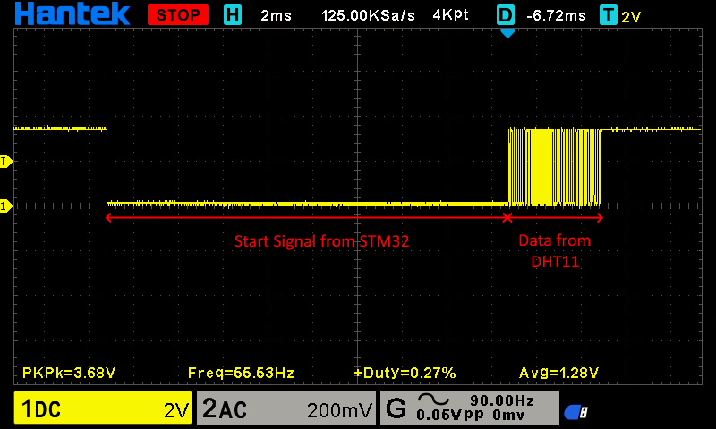
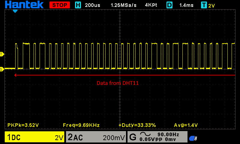
With an oscilloscope probe on the data pin of the DHT11, we can see this behaviour (images taken utilising the completed driver):
Microsecond Accuracy
As such, it is clear that microsecond timing is a key part in communicating with the DHT. To work on such a time scale, we can’t used the HAL_Delay function as it only offers pausing at a minimum of 1 millisecond (1000 microseconds).
As such, we’ll have the utilise the STM32’s Data Watchpoint and Trace (DWT) unit which allows us to get the CPU’s current cycle count, which we can use to calculate the required number of CPU cycles to surpass a certain microsecond time period. With this, we can delay for a certain number of microseconds, and also time signals in microseconds.
I found this really useful article which outlined how to implement a DWT microsecond delay function: kbiva.wordpress.com [3].
// --- Initialise the DWT ---
// Initates the DWT (Data Watchpoint and Trace) unit (if not already initiated)
// Used for microsecond timing
static void DWT_Init(void) {
    if (!(DWT->CTRL & DWT_CTRL_CYCCNTENA_Msk)) {
        CoreDebug->DEMCR |= CoreDebug_DEMCR_TRCENA_Msk;
        DWT->CTRL |= DWT_CTRL_CYCCNTENA_Msk;
    }
}

// --- Delay for microseconds ---
static void delay_us(uint32_t us) {
    uint32_t start = DWT->CYCCNT; // get the current cycle count
    uint32_t ticks = us * (SystemCoreClock / 1000000); // calculate how many CPU cycles represent the required us delay
    while ((DWT->CYCCNT - start) < ticks); // do nothing (wait) until the required number of ticks for the us delay have been achieved
}Pin Switching
The DHT11 only has a single data pin, and this is used for both talking and listening to the DHT11. As an GPIO pin can only be an input or an output at one time, I created a function to set the mode of the data pin.
When we are wanting to trigger a read out, we need to talk to the DHT11, so we configure the GPIO pin as an output and re-initiate the GPIO.
When listening to what the DHT11 is reading out, we must set it to an input so we can actually read the data. Some sources state that a pull up is required, but it worked just fine for me without an internal or external pull up, but the choice to add an internal one is left up to you in the code.
// --- Pin Mode Switching ---
static void set_input(void) {
GPIO_InitTypeDef GPIO_InitStruct = {0};
GPIO_InitStruct.Pin = DHT11_PIN;
GPIO_InitStruct.Mode = GPIO_MODE_INPUT;
GPIO_InitStruct.Pull = GPIO_NOPULL; // Works for me without internal or external pull up. External may be required for some models?
HAL_GPIO_Init(DHT11_PORT, &GPIO_InitStruct);
}
static void set_output(void) {
GPIO_InitTypeDef GPIO_InitStruct = {0};
GPIO_InitStruct.Pin = DHT11_PIN;
GPIO_InitStruct.Mode = GPIO_MODE_OUTPUT_PP;
GPIO_InitStruct.Pull = GPIO_NOPULL;
GPIO_InitStruct.Speed = GPIO_SPEED_FREQ_LOW;
HAL_GPIO_Init(DHT11_PORT, &GPIO_InitStruct);
}Readings
As we know from the communication protocol, the DHT11 encodes it’s binary output in a HIGH pin state on the data pin, with a different HIGH duration indicating a 0 or a 1. The LOW pin state is purely for indicating the end of that duration, so we can read out more than one bit.
As the LOW pin state is purely a separator, we don’t need to time that, we only have the time how long the data pin is HIGH for.
To do so, I implemented a wait_for_input_state function which measures how long it takes for the input state to change. This is reusing some code from the delay_us function.
// --- Pulse Duration Measurement ---
static uint32_t wait_for_input_state(uint8_t state, uint32_t timeout_us) {
uint32_t start = DWT->CYCCNT; // get current cycle count
uint32_t ticks = timeout_us * (SystemCoreClock / 1000000); // get the number of ticks for the timeout
while ((DWT->CYCCNT - start) < ticks) {
if (HAL_GPIO_ReadPin(DHT11_PORT, DHT11_PIN) == state) {
return (DWT->CYCCNT - start) / (SystemCoreClock / 1000000);
}
}
return 0xFFFFFFFF; // timeout
}With this, we now can distinguish a 0 from a 1, but we don’t have any way to actually facilitate the full reception.
Let’s create the decoding protocol in code.
First we have to send the start signal -> the data pin is set to an output, we pull it low for 18ms and then back to high.
set_output();
HAL_GPIO_WritePin(DHT11_PORT, DHT11_PIN, GPIO_PIN_RESET); // pull low
delay_us(18000); // for 18 ms
HAL_GPIO_WritePin(DHT11_PORT, DHT11_PIN, GPIO_PIN_SET); // pull high
delay_us(20); // short delayNext, we listen to what the DHT11 has to say -> the data pin is set as an input, and we read the “I heard you!” response from the DHT11. The timing of the response isn’t exactly mission critical, so I just use 100us as the cut-off. There’s a checksum at the end for the data anyway, and that’s all we really care about.
set_input();
// Require LOW (54us) then HIGH (80us)
if (wait_for_input_state(GPIO_PIN_RESET, 100) == 0xFFFFFFFF) return DHT11_ERROR_NO_RESPONSE; // require LOW
if (wait_for_input_state(GPIO_PIN_SET, 100) == 0xFFFFFFFF) return DHT11_ERROR_NO_RESPONSE; // require HIGH
// Require LOW (the start of data)
if (wait_for_input_state(GPIO_PIN_RESET, 100) == 0xFFFFFFFF) return DHT11_ERROR_TIMEOUT; // require LOWNow we start listening to the actual data from the DHT11 -> 5 bytes is 40 bits we listen out for, timing how long each HIGH pulse of the data pin is.
For each bit, we initially wait for the data pin to go HIGH, indicating the start of the bit, and then wait for it to go LOW again – this time until LOW is what we are measuring to distinguish the bit’s value.
if (wait_for_input_state(GPIO_PIN_SET, 70) == 0xFFFFFFFF) return DHT11_ERROR_TIMEOUT;
uint32_t held = wait_for_input_state(GPIO_PIN_RESET, 100);
if (held == 0xFFFFFFFF) return DHT11_ERROR_TIMEOUT;If the hold time is greater than 40us, then we can safely assume that the bit is a 1, and if not, a 0. I then put this read bit into the array of bytes. As its an array of bytes, its only contains 5 elements, so we have to insert the next LSB into the byte. This is done by left shifting all the bits in the byte, opening up the LSB for entry, and using the bitwise OR assignment operator to insert the new bit into the LSB of the byte. (More info in the source code comments)
uint8_t bit = (held > 40) ? 1 : 0; // if was held for >40us, then its a 1, less than 40us, its a 0
data[i / 8] <<= 1;
data[i / 8] |= bit;To visualise this, here is the process of writing the bits 1, 0, and finally 1:
data[0] <<= 1; // --> data[0] = 00000000 << 1 = 00000000
data[0] |= 1; // --> data[0] = 00000000 | 00000001 = 00000001
data[0] <<= 1; // --> data[0] = 00000001 << 1 = 00000010
data[0] |= 0; // --> data[0] = 00000010 | 00000000 = 00000010
data[0] <<= 1; // --> data[0] = 00000010 << 1 = 00000100
data[0] |= 1; // --> data[0] = 00000100 | 00000001 = 00000101Finally, we calculate what the checksum is based on the data we received, and compare it with the checksum the DHT11 told us is correct.
If the checksum is fine, we know we read the data without corruption, so we assign the read data values to the pointers provided to the function, outputting the readings.
// Checksum byte should be the sum of all data bytes
uint8_t checksum = data[0] + data[1] + data[2] + data[3];
if (checksum != data[4]) return DHT11_ERROR_CHECKSUM;
*humidity_int = data[0];
*humidity_dec = data[1];
*temperature_int = data[2];
*temperature_dec = data[3];
return DHT11_OK; // Successfully read the DHT11This whole process is then repeated 39 more times, so we read all 40 bits.
Status Enumeration
As you may have noticed in the reception code, I’m outputting some “error codes”, like DHT11_ERROR_TIMEOUT or DHT11_ERROR_CHECKSUM.
If we look in the header file for this driver, I defined an enumeration outlining each status code for the driver. This gives us an easy and human readable way to access how the read went.
This is why the datatype of the DHT11_Read function is DHT11_Response, and its parameters are pointers. It returns a single status code, and modifies variables outside of itself to actually output the readings.
#ifndef DHT11_H
#define DHT11_H
#include "stm32g4xx_hal.h"
// Emum to describe read status
typedef enum {
DHT11_OK = 0,
DHT11_ERROR_TIMEOUT,
DHT11_ERROR_CHECKSUM,
DHT11_ERROR_NO_RESPONSE
} DHT11_Response;
// --- Functions ---
// Defines the GPIO pin and port for the DHT11
void DHT11_Setup(GPIO_TypeDef* port, uint16_t pin);
// Initiates and reads a response from the DHT11
DHT11_Response DHT11_Read(uint8_t* temperature_int, uint8_t* temperature_dec, uint8_t* humidity_int, uint8_t* humidity_dec);
#endifThe Final Driver
Let’s take a look at the full source file now:
#include "sensors/dht11.h"
// Sources:
// https://www.engineersgarage.com/articles-arduino-dht11-humidity-temperature-sensor-interfacing/
// https://kbiva.wordpress.com/2013/03/25/microsecond-delay-function-for-stm32/
// Variables
static GPIO_TypeDef* DHT11_PORT;
static uint16_t DHT11_PIN;
// --- Initialise the DWT ---
// Initates the DWT (Data Watchpoint and Trace) unit (if not already initiated)
// Used for microsecond timing
static void DWT_Init(void) {
    if (!(DWT->CTRL & DWT_CTRL_CYCCNTENA_Msk)) {
        CoreDebug->DEMCR |= CoreDebug_DEMCR_TRCENA_Msk;
        DWT->CTRL |= DWT_CTRL_CYCCNTENA_Msk;
    }
}

// --- Delay for microseconds ---
static void delay_us(uint32_t us) {
    uint32_t start = DWT->CYCCNT; // get the current cycle count
    uint32_t ticks = us * (SystemCoreClock / 1000000); // calculate how many CPU cycles represent the required us delay
    while ((DWT->CYCCNT - start) < ticks); // do nothing (wait) until the required number of ticks for the us delay have been achieved
}
// --- Pin Mode Switching ---
static void set_input(void) {
    GPIO_InitTypeDef GPIO_InitStruct = {0};
    GPIO_InitStruct.Pin = DHT11_PIN;
    GPIO_InitStruct.Mode = GPIO_MODE_INPUT;
    GPIO_InitStruct.Pull = GPIO_NOPULL; // Works for me without internal or external pull up. External may be required for some models?
    HAL_GPIO_Init(DHT11_PORT, &GPIO_InitStruct);
}

static void set_output(void) {
    GPIO_InitTypeDef GPIO_InitStruct = {0};
    GPIO_InitStruct.Pin = DHT11_PIN;
    GPIO_InitStruct.Mode = GPIO_MODE_OUTPUT_PP;
    GPIO_InitStruct.Pull = GPIO_NOPULL;
    GPIO_InitStruct.Speed = GPIO_SPEED_FREQ_LOW;
    HAL_GPIO_Init(DHT11_PORT, &GPIO_InitStruct);
}
// --- Pulse Duration Measurement ---
static uint32_t wait_for_input_state(uint8_t state, uint32_t timeout_us) {
    uint32_t start = DWT->CYCCNT; // get current cycle count
    uint32_t ticks = timeout_us * (SystemCoreClock / 1000000); // get the number of ticks for the timeout

    while ((DWT->CYCCNT - start) < ticks) {
        if (HAL_GPIO_ReadPin(DHT11_PORT, DHT11_PIN) == state) {
            return (DWT->CYCCNT - start) / (SystemCoreClock / 1000000);
        }
    }
    return 0xFFFFFFFF; // timeout
}
// --- Initiate the DHT11 ---
static void DHT11_Init(void) {
DWT_Init();
set_output();
HAL_GPIO_WritePin(DHT11_PORT, DHT11_PIN, GPIO_PIN_SET); // set pin to HIGH
}
// --- SETUP DHT11 ---
/**
* @brief Sets up the GPIO configuration for the DHT11 sensor.
*
* This function configures the specified GPIO port and pin for the DHT11 sensor,
* enabling the clock for the GPIO port if needed. After setup, it initialises the
* DHT11 sensor.
*
* @param port: Pointer to the port where the DHT11 data pin is connected (e.g., GPIOA, GPIOB, GPIOC).
* @param pin: Pin number of the GPIO port where the DHT11 data pin is connected.
*/
void DHT11_Setup(GPIO_TypeDef* port, uint16_t pin) {
DHT11_PORT = port;
DHT11_PIN = pin;
// Enable the ports peripheral clock
if (port == GPIOA) __HAL_RCC_GPIOA_CLK_ENABLE();
else if (port == GPIOB) __HAL_RCC_GPIOB_CLK_ENABLE();
else if (port == GPIOC) __HAL_RCC_GPIOC_CLK_ENABLE();
DHT11_Init();
}
// --- MAIN READ FUNCTION ---
/**
* @brief Reads temperature and humidity (int and dec) from the DHT11 sensor.
*
* This function initiates communication with the DHT11 sensor and reads the temperature and humidity values.
* It requires a successful setup of the DHT11 sensor through DHT11_Setup() before calling this function.
*
* @pre DHT11_Setup(port, pin) must be called before using this function.
*
* @param temperature_int: Pointer to store the integer part of the temperature (°C).
* @param temperature_dec: Pointer to store the decimal part of the temperature (some DHT11 models will just be 0).
* @param humidity_int: Pointer to store the integer part of the humidity (%RH).
* @param humidity_dec: Pointer to store the decimal part of the humidity (some DHT11 models will just be 0).
*
* @retval DHT11_OK: If the data was read successfully.
* @retval DHT11_ERROR_NO_RESPONSE: If the sensor did not respond.
* @retval DHT11_ERROR_TIMEOUT: If a timeout occurred while reading data.
* @retval DHT11_ERROR_CHECKSUM: If the checksum does not match.
*
*/
DHT11_Response DHT11_Read(uint8_t* temperature_int, uint8_t* temperature_dec, uint8_t* humidity_int, uint8_t* humidity_dec) {
// Create the data array to store the bytes
uint8_t data[5] = {0}; // 5 bytes = 40 bits
// 1. Send the start signal
set_output();

HAL_GPIO_WritePin(DHT11_PORT, DHT11_PIN, GPIO_PIN_RESET); // pull low
delay_us(18000); // for 18 ms
HAL_GPIO_WritePin(DHT11_PORT, DHT11_PIN, GPIO_PIN_SET); // pull high
delay_us(20); // short delay
// 2. Read response
set_input();
// Require LOW (54us) then HIGH (80us) (but exact timing doesn't matter, checksum will be there to see if it was successful)
if (wait_for_input_state(GPIO_PIN_RESET, 100) == 0xFFFFFFFF) return DHT11_ERROR_NO_RESPONSE; // require LOW
if (wait_for_input_state(GPIO_PIN_SET, 100) == 0xFFFFFFFF) return DHT11_ERROR_NO_RESPONSE; // require HIGH
// Require LOW (the start of data)
if (wait_for_input_state(GPIO_PIN_RESET, 100) == 0xFFFFFFFF) return DHT11_ERROR_TIMEOUT; // require LOW
// 3. Read 5 bytes = 40 bits
// Each bit starts with LOW for 54us, then HIGH: 24us is a bit 0, 70us is a bit 1
for (int i = 0; i < 40; i++) {
if (wait_for_input_state(GPIO_PIN_SET, 70) == 0xFFFFFFFF) return DHT11_ERROR_TIMEOUT; // Start of bit is LOW, so wait for HIGH (which actually tells us what the bit is)
uint32_t held = wait_for_input_state(GPIO_PIN_RESET, 100); // Now that the pin is HIGH, wait until it goes LOW and count how long it takes for it to do so
if (held == 0xFFFFFFFF) return DHT11_ERROR_TIMEOUT;
uint8_t bit = (held > 40) ? 1 : 0; // if was held for >40us, then its a 1, less than 40us, its a 0
data[i / 8] <<= 1; // i is current bit index, i / 8 is current byte index (8 bits in 1 byte), <<= 1 shifts the current byte left by 1 to make room for the new byte at LSB
data[i / 8] |= bit; // bit is either 0 or 1, |= is bitwise OR assignment operator, inserts new bit into the LSB of the byte
// Example for the above bit writing (writing bits 1, 0, and then 1):
// data[0] <<= 1; --> data[0] = 00000000 << 1 = 00000000
// data[0] |= 1; --> data[0] = 00000000 | 00000001 = 00000001
// data[0] <<= 1; --> data[0] = 00000001 << 1 = 00000010
// data[0] |= 0; --> data[0] = 00000010 | 00000000 = 00000010
// data[0] <<= 1; --> data[0] = 00000010 << 1 = 00000100
// data[0] |= 1; --> data[0] = 00000100 | 00000001 = 00000101
}
// 4. Check the checksum to ensure a valid reading
// Checksum byte should be the sum of all data bytes
uint8_t checksum = data[0] + data[1] + data[2] + data[3];
if (checksum != data[4]) return DHT11_ERROR_CHECKSUM;

*humidity_int = data[0];
*humidity_dec = data[1];
*temperature_int = data[2];
*temperature_dec = data[3];

return DHT11_OK; // Successfully read the DHT11
}Testing
Let’s test it out. I modified main.c to read the DHT11 every 2 seconds, and output its read value over USB serial. I implemented a println function in the usb_serial module as well.
#include "sensors/dht11.h"/* USER CODE BEGIN Init */
DHT11_Setup(GPIOB, GPIO_PIN_0); // setup DHT11 on pin B0
/* USER CODE END Init *//* USER CODE BEGIN WHILE */
uint8_t temp_int = 0, temp_dec = 0, hum_int = 0, hum_dec = 0;
while(1) {
char msg[64];
DHT11_Response response = DHT11_Read(&temp_int, &temp_dec, &hum_int, &hum_dec);
if (response == DHT11_OK) {
sprintf(msg, "Temp: %d.%dC, Humidity: %d.%d%", temp_int, temp_dec, hum_int, hum_dec);
} else if (response == DHT11_ERROR_TIMEOUT) {
sprintf(msg, "DHT11_ERROR_TIMEOUT");
} else if (response == DHT11_ERROR_CHECKSUM) {
sprintf(msg, "DHT11_ERROR_CHECKSUM");
} else if (response == DHT11_ERROR_NO_RESPONSE) {
sprintf(msg, "DHT11_ERROR_NO_RESPONSE");
}
usb_serial_println(msg); // Custom wrapper function
HAL_Delay(2000);
}
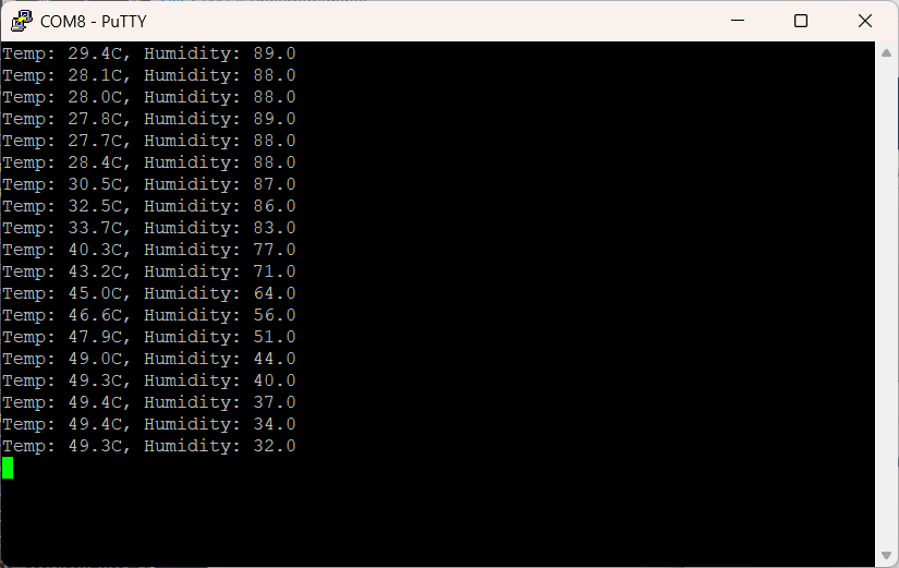
/* USER CODE END WHILE */After building the project and uploading it to the dev board, we get the following output after establishing a serial connection over USB with the microcontroller:
References
[1] “DHT11 basic temperature-humidity sensor + extras,” Adafruit. https://www.adafruit.com/product/386
[2] “Arduino compatible coding 15: Reading sensor data from DHT-11 without using a library”, Nikhil Agnihotr – Engineers Garage. https://www.engineersgarage.com/articles-arduino-dht11-humidity-temperature-sensor-interfacing/
[3] “Microsecond delay function for STM32,” KBIVA. https://kbiva.wordpress.com/2013/03/25/microsecond-delay-function-for-stm32/