Introduction


Note: This is an archive of my Year 10 Semester 1 STEM Project (2021). The powerpoint slides have been converted to article form. Everything but a few stock photos (so I can give an updated source) remains unchanged from the original presentation.
For my Year 10 S1 STEM Project, I wanted to expand upon one of my previous years project: the DIY Arduino using an ATMega328P micro-controller IC, and an array of complementary components to allow it to function as an Arduino. In this project, I set out to design an all-in-one, stepper motor driver board using the ULN2003 stepper motor driver ICs. This IC choice was made because I wanted to be able to control the very inexpensive 28BYJ-48 uni-polar stepper motors with very inexpensive driver ICs.
I learnt a lot in this project such as circuit reverse engineering, circuit debugging, schematic and PCB design, and it was my first time designing and soldering with SMD components.
Presentation
Stepper Motor Controller Board for CNC applications
The Idea
A CNC control board is a piece of hardware that enables a computer to interface with stepper motors. I’d like to build an all in one board for controlling a specific type of cheap stepper motors to remove the need for separate controllers for each motor and a separate Arduino board.
A stepper motor is a motor designed for moving precise distances/turning a precise amount. This is possible because you can tell the stepper motor to move a number of steps which equates to a distance in real life. However, stepper motors need dedicated driver boards to control them as they have multiple coils that need to be powered in a specific pattern to create movement. That is why a board is required.
What is it:
• Hardware used to control stepper motors
• Can be controlled by plugging into a computer
or adding an SD Card Module.
Stepper Motors:
• Used for turning a precise amount.
• Can’t just be powered from a battery like
the usual DC motors (this is why it needs a
controller board).

Image Source: core-electronics

Image Source: core-electronics
Research
Before I started designing, I had to figure out the different stages of communication that had to occur between different parts:


Figure 4. Other commercially available stepper motor driver boards that I’ve used in the past:
Creating the First Prototype
The design process was the longest process of this project as many different iterations had to be made.
Creating the first prototype first involved creating the schematic (drawing of the circuit).

About Stepper Motors
Stepper motors are DC motors that move in discrete steps.
They have multiple coils that are organized in groups called “phases”. By energizing each phase in sequence, the motor will rotate, one step at a time. With a computer controlled stepping you can achieve very precise positioning and/or speed control. For this reason, stepper motors are used in machines such as 3D printers and CNC mills.

Source: I cannot recall if I made these annotations in the photo or not, but the stock image is from: Pololu
Creating the First Prototype
The next stage was laying out these components from the schematic on a board file which is used to order the final PCB.

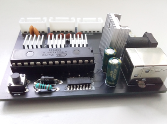
When the PCB and components arrived, I soldered everything onto the board.


Issues with First Prototype
Important Issues to fix:
- No communication between CH340G and ATMega328P (RX and TX flipped)
- No power to ATMega328P (forgot to connect to net)
- Net Classes weren’t allocated to traces + forgot ground plane
- Forgot to add decoupling capacitors
Less Important but I still wanted to fix:
- Poor Layout: Was hard to remove ATMega328p from socket once inserted due to arrangement of components
Fixing these issues – Second Prototype
To fix these issues, I first deleted the board file and then fixed everything in the schematic. Some additions I made: RX and TX indicator LEDs, Sockets connected to the pins of the AtMega for debugging purposes (and potentially add-ons).


Second Prototype
Once I had ordered the new PCB, I again assembled everything.
Then I powered it up and attempted to flash the GRBL firmware via the Arduino IDE which succeeded meaning the issues (so far) have been fixed:

Testing the Second Prototype
Skills I learnt
- A better understanding of how different simple components interact with each other (e.g. how to add decoupling capacitors and why they’re important.)
- A better understanding of the building blocks of microcontrollers (USB-Serial, Main IC, etc.)
- How to design schematics and PCB’s (boards) in Eagle.
- How to solder SMD components (ICs & LEDs)
Things I could improve
- Improve the power regulation (find a different strategy to increase efficiency and
decrease heat production) - Make it easier to use – decrease the amount of software configuration required
- Add a few more inputs – Limit Switches, Probe, etc.
- Add a 4th (and potentially 5th) driver for capacity of 2 extra motors (Ramps1.4 has support for 5 total steppers).